Fit one of our BAFE Certified Fire Alarms to keep Lives & Property Safe.
Fire Detection Specialists
Fire Alarm System Information
Usage
Home Office statistics indicate that every year there are more than 100,000 fires in buildings, and some 600 people lose their lives in these fires. The suffering and financial loss are excessive. We have more than 35 years of practical experience in protecting people and property from fire. We use technology that ensures fires are detected faster thereby minimising the damage they cause.
Fire Alarm Systems
The choice of fire alarm system depends on the building structure, the purpose and use of the building and current legislation. In new or altered buildings the enforcement body is the local building control, and the relevant guidance is explained in section new or altered buildings. All existing buildings except domestic premises are subject to The Regulatory Reform (Fire Safety) Order and the Responsible Person, as defined in the order, has to conduct a fire risk assessment. This Assesment will decided the appropriate British Standard necessary to provide a suitable and sufficient solution for the premises. The enforcement body is the Fire and Rescue Service and the Department of Communities and Local Government have published a number of guidance documents for premises subject to the Order. This is particularly important since none of the legislation gives any detailed information on the type of system required but the guidance usually indicates appropriate British standards. The main standard for fire alarm systems is BS5839 pt1.
The following contains brief descriptions of the major components which go to make up a fire alarm system. The points to be considered are intended to highlight the variables which can exist and need to be considered whilst designing and compiling a specification for component parts.
Types of Fire Alarm Systems
 All Fire Alarm Systems essentially operate on the same principle. If a detector detects smoke or heat or someone operates a break glass unit (manual break point), then alarm sounders operate to warn others in the building that there may be a fire and to evacuate. It may also incorporate remote signaling equipment which would alert the fire brigade via a central station.
Fire Alarm Systems can be broken down into four types:
- Conventional
- Analogue Addressable
- Addressable
- Wireless systems
Conventional Fire Alarm System
In a Conventional Fire Alarm System, a number of call points and detectors are wired to the Fire Alarm Control Panel in Zones. A Zone is a circuit and typically one would wire a circuit per floor or fire compartment. The Fire Alarm Control Panel has a number of Zone Lamps. The reason for having Zones is to give a rough idea as to where a fire has occurred. This is important for the fire brigade and of course for the building management. The accuracy of knowing where a fire has started is controlled by the number of Zones a Control Panel has and the number of circuits that have been wired within the building. The Control Panel is wired to a minimum of two sounder circuits which could contain bells, electronic sounders or other audible / visual devices. Each circuit has an end of line device which is used for monitoring purposes.
Addressable Systems
The detection principle of an Addressable System is similar to a Conventional System except that the Control Panel can determine exactly which detector or call point has initiated the alarm. The detection circuit is wired as a loop and up to 99 devices may be connected to each loop. The detectors are essentially Conventional Detectors, with an address built in. The address in each detector is set and the Control Panel is programmed to display the information required when that particular detector is operated. Additional Field Devices are available which may be wired to the loop for detection only i.e. it is possible to detect a normally open contact closing such as sprinkler flow switch, or a normally closed contact opening. Sounders are wired in a minimum of two sounder circuits exactly as a Conventional System. Loop Isolation Modules are available for fitting on to the detection loop/loops such that the loop is sectioned in order to ensure that a short circuit, or one fault will only cause the loss of a minimal part of the system.
Analogue Addressable Fire Alarm Systems
Analogue Addressable Fire Alarm Systems are often known as Intelligent Fire Alarm Systems. There are several different types of Analogue Systems available which are determined by the type of protocol which they use. The bulk of standard Analogue Detectors available give output signals representing the value of detected phenomena. It is left up to the Control Unit to decide whether there is a fire, fault, pre-alarm or other. With a true Intelligent Analogue System each detector effectively incorporates its own computer which evaluates the environment around it, and communicates to the Control Panel whether there is a fire, fault or the detector head needs cleaning. Essentially Analogue Systems are far more complex and incorporate far more facilities than Conventional or Addressable Systems. Their primary purpose is to help prevent the occurrence of false alarms. With the Analogue Addressable System, up to 127 input devices i.e.: Smoke Detectors, Call Points, Heat Detectors, Contact Monitors and other interface devices may be wired to each detection loop. In addition to the 127 Input Devices, up to 32 Output Devices such as Loop Sounders, Relay Modules and Sounder Modules may be connected. Analogue Systems are available in 2, 4 and 8 loop versions which means large premises can be monitored from one single panel. Isolator units should be connected between sections of detectors as described for Addressable Systems.
Wireless Fire Alarm System
Wireless fire alarm systems are an effective alternative to traditional wired fire alarm systems for all applications. They utilise secure, licence-free radio communications to interconnect the sensors and devices (smoke detectors, call-points, etc.) with the controllers. It is a simple concept, which provides many unique benefits and is a full analogue addressable fire detection system without the need for cable.
System Design
Before starting, the designer will need to ensure that certain information is available. This may be given in the specification or it may have to be obtained by consultation. As well as the purchaser, there may be a requirement to consult with other interested parties
Points to consider
- The type of system required i.e. L1, L2, L3 etc and where appropriate, parts of the premises to be covered.
- The action to be taken in the event of fire
- Whether other occupants of a multi occupancy building will be affected
- Whether other work is to be done at the same time. If so then consultation with other contractors may be required.
- A Method of calling the Fire Brigade
- Whether the type of occupants or activity in the building will require a greater provision of Manual Call Points than normal
- A likely attendance time of the Fire Brigade
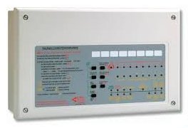
Control of Indicating Panels
Control and indicating equipment performs three principal functions, namely:
- Automatic monitoring and control of circuits external to the equipment, such as fire detection and fire alarm device circuits and supply of power to these circuits
- Indication of fire signals, fault signals and their location
- Manual control to facilitate actions such as testing, disablement of devices, triggering of fire signals, silencing of audible fire warnings and resetting the system after a fire signal
Panels are fully specified in British Standards. This requires that circuits are monitored continuously and that both audible and visual indication is provided for fault and fire alarm conditions. Further requirements include that alarm sounders may only be silenced manually, after which the control panel must provide audible and visual signals until the system is reset. Silencing of alarm sounders must not prevent the alarm being raised in other zones. It should be noted that the standards require all fault/alarm indicator lamps to be in duplicate or a single lamp with audible signal of lamp failure. Control and indicating panels may include facilities for operation of ancillary services such as fixed fire extinguishing, door closing etc.
The equipment should normally be sited in an area of low fire risk and on the ground floor by the entrance used by the Fire and Rescue Service and preferably viewable from outside of the building. It should be located in an area common to all building users and where automatic detection is in use, the Control Panel should be in a protected area. An alarm sounder should be sited next to the Control Unit, but not too near the telephone position. A suitable zone chart of the building should normally be installed adjacent to the Control Panel.
Points to consider
- Number of zones required
- Surface or flush mounting
- Maximum alarm load per alarm zone
- Automatic system, compliance with British Standard
- Manual system compliance with British Standard
- Maximum current per detector zone
- Maximum detectors per zone
- Open, closed or fault monitored system
- Single or two stage alarms
- Provision for connection to remote manned centre
- Provision for conduit and wiring compatible with
building conduit and wiring system
- Provision for operation of ancillary services
Detector Heads
These can be divided into four main types Heat detectors, Smoke detectors, Carbon Monoxide detectors and Multi sensors detectors.
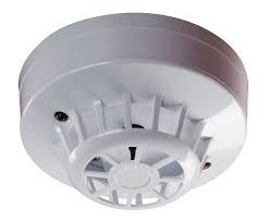
Heat detectors
Heat sensitive point detectors
Point detectors can again be subdivided to a further two
types.
- Fixed temperature which will operate when it is exposed to a pre-determined temperature. Normally fixed temperature detectors employ a fusible alloy element which must be replaced after the detector has operated. Different temperature rated elements are available to take account of varying ambient air temperatures.
- The second type operates on the rate of temperature rise. The rate of rise temperature detector may also include a fusible element for fixed temperature operation.
Both types are suitable for inclusion in open, closed or line monitored systems.
Linear detectors
These can take the form of a heat sensitive cable which will operate, at a predetermined temperature, as an open circuit device. Melting of the cable insulation provides a short-circuit between conductors. After operation the destroyed length of cable must be replaced. Linear detectors may be used in large areas such as warehouses. Alternative types of linear detector exist including the heat pneumatic operating on the
rate of rise principle.
Points to consider
- Open, closed, fault monitored circuits
- Temperature setting for fixed temperature fusible elements
- Spare fusible elements
- Surface or flush mountings
- Temperature setting for fusible elements in the rate of rise detection., if included
- Mounting height
- Spacing to manufacturer’s recommendations
- Rate of rise detectors located in positions where abnormal increase in temperature is likely, e.g. space heating equipment, industrial processes
Smoke Detectors
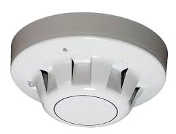
There are three basic types operating by ionization, light scattering and light obscuring.
Ionisation
These generally contain two chambers. One is used as a reference to compensate for changes in ambient temperature, humidity or pressure. The second contains a radioactive source, usually alpha particle, which ionizes the air passing through the chamber where a current flows between two electrodes. When any of the products of combustion enters the chamber the current flow decreases. This drop is used to initiate an alarm.
Light obscuring
In the obscuring type the smoke interferes with a light beam between a light source and photo cell, the variation in photo cell output being used to initiate an alarm. This type of detection can be used to protect large areas with the source and photo cell positioned some distance apart.
Light scattering
The light scattering detector operates on the Tyndall effect, a photo cell and light source are separated from each other by a darkened chamber such that the light source does not fall on the photo cell. The passage of smoke into the chamber causes the light from the source to be scattered and fall on the photo cell, the cell output being used to initiate an alarm.
The light scattering and light obscuring detectors both, detect visible smoke. The ionization detector and light scattering detector are normally each a single unit suitable for BESA conduit box mounting. In some models the smoke detector head is attached to the main body by a bayonet fixing for easy removal for maintenance or replacement. It should be noted that some detectors are suitable for two-wire circuits whereas others require three or four wire connections. Smoke detectors require a continuous power supply. Under quiescent conditions they draw a current of some 100 micro amps, and under alarm conditions, some 45 milliamps. This needs to be borne in mind when sizing the power supply. Smoke detectors generally operate on 24 d.c. Refer to British Standard Codes of Practice and manufacturers literature for information regarding the positioning of smoke detectors. Detectors are not suitable for positioning in kitchens, near fireplaces or areas with excessive exhaust fumes, or within 2m of air supply ducts or diffusers.
Carbon Monoxide detector
CO fire detectors are electronic detectors used to indicate the outbreak of fire by sensing the level of carbon monoxide in the air. Carbon monoxide, usually known by its chemical formula CO, is a poisonous gas produced by combustion. They are not the same as CO detectors used for home safety which are used to protect residents against carbon monoxide produced by incomplete combustion in appliances such as gas fires or boilers.
CO fire detectors use the same type of sensor but are more sensitive and respond more quickly.CO detectors have an electrochemical cell, which senses carbon monoxide, but not smoke or any other combustion products. The cells do not require much power, so the detectors can be made electrically compatible with ordinary smoke and heat detectors. As fire detectors they are effective but only for certain types of fire. Deep-seated, smouldering fires produce carbon monoxide, which can be detected some distance from the seat of the fire. For this type of fire a CO fire detector will probably operate before a smoke detector. Smoke detectors, however, will almost always give a better response to a fire that has produced a rising plume of smoke. CO fire detectors will give a poor response to flaming fires. Because CO fire detectors work on different principles from smoke detectors, their false alarm behaviour will be different. For example, they will not be affected by steam, dust, or by most cooking fumes. However, because of their high sensitivity, they may false alarm from harmless transient levels of CO produced by gas heaters starting up, or from vehicle exhaust fumes entering through a window. These events would not affect an optical smoke detector.
As always, the detector must be selected for the application, to achieve the best balance between fire detection capability and false alarms. There are some known disadvantages of CO fire detectors. One is that the electrochemical cells at the heart of the detectors have a limited life typically seven years and that they are not failsafe. The detector might be non-functional with out this fact being apparent. For this reason a means of checking the CO cell has been incorporated. Another clear disadvantage is the poor response to many types of fire, especially life threatening flaming fires.
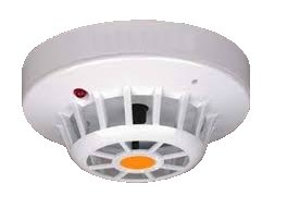
Multi sensor detector
This detector combines inputs from optical and heat sensors and processes them using a sophisticated algorithm. When polled by the control panel it returns an analogue count which is determined by combined responses from both optical and heat sensors. They are designed to be sensitive to a wide range of fires and may be used in place of an ionisation detector in many instances.
Operating principles
Signals from the optical smoke chamber and temperature sensor are independent, and represent the smoke level and air temperature respectively in the vicinity of the detector; the detectors micro controller processes both signals. The temperature signal processing extracts only rate of rise information for combination with the smoke signal. The detector will not respond to slow increases in temperature but a large sudden change can cause an alarm without presence of smoke, if sustained for 20 seconds. The processing algorithms in the multi-sensor incorporate drift compensation.
Points to consider
- Open or closed circuit
- Fault monitored circuit
- System voltage
- Surface or flush mounting
- Detector operated indicator
- Two or three-wire system
- Quiescent current demand
- Smoke detector location
- Spare detector heads
Manual Call Points
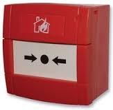 A Break Glass Call Point is a device which enables personnel to raise the alarm by breaking the frangible element on the fascia. They should be mounted 1.4m from the floor and sited where they can be easily seen. Manual Call Points should be sited on the floor landings of stairways and at exits to open air. It should be noted that Call Points should be fitted on the floor side of an access door to a staircase so the floor of origin is indicated at the Control Panel. Extra points should be sited, where necessary, so that the greatest travel distance from any point in the building to the nearest call point does not exceed 30m. A greater number of Call Points may be needed in high risk areas or if the occupants are likely to be slow in movement. Flameproof call points are available, also handle operated points for use in areas where broken glass may cause a hazard.
Points to consider
- Open circuit, closed circuit, fault monitored circuit
- Surface, flush mounting
- Weatherproof, internal location
- Spare breakable material
- Contact rating suitable for load under alarm conditions
- Special call points for flameproof or special hazard areas
- Hammer for call points with breakable front plates
Alarm Sounders
- Dome bells – operating mechanism contained within the bell.
- Bells with operating mechanism external to the bell.
- Electronic solid state sounders with mono or multi tone output normally in the range of 800 – 1000 Hz.
- Small sirens operating in the range of 1,200 – 1,700 Hz.
- Sirens ranging widely in size from 0.17kw to 11kW generally operating in the frequency range of 400 – 800 Hz.
- Horns operating in the range of 300 – 400 Hz and either motor or pneumatic operations.

Many types of alarm sounders are available and include:
The following figures gives a broad indication of the sound levels of the various alarm sounders. Also indicated are typical sound levels for various industrial and commercial situations. An alarm noise level of not less than 5 decibels above ambient should be provided in general areas for adequate audibility but in sleeping areas a minimum level in the order of 65 decibels and 75 decibels at a bed head to wake sleeping occupants. For surface wiring or conduit installations surface mounting adaptor boxes are normally required. Generally bells, electronic sounders and small sirens are available for use with 6, 12, 24 and 48V d.c. Sirens are normally operated at mains voltage. Public address systems may be used where necessary.
Points to consider
- Operating voltage
- Installation with surface or flush conduit system
- Internal or weather-proof installations
- Bell gong size
- Colour
- Motor rating of sirens, note some sirens are rated for continuous duty whilst others are rated for limited time periods.
- Television interference suppression

Whisper at three feet = 30dB
Casual conversation at three feet = 65dB
Threshold of pain = 130dB

Visual Alarm Devices
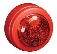
In Buildings that have high noise thresholds and in public buildings where hearing impaired individuals may be present Visual Alarm Devices are used to ensure that the Fire alert is recognised.
Power Units
Two power supplies are required i.e. mains and battery and these are normally built into the Fire Alarm Control Panel. Standby batteries must allow the system to operate without mains for 24 hours longer than the building is likely to be unoccupied and then support the sounders for an additional half hour. If the mains supply is supported by an emergency generator then six hours standby plus half an hour alarm load is sufficient. All modern Fire Alarm Systems are 24 volts. On the medium and larger sized Fire Alarm Systems, the standby batteries will often not fit within the Control Panel. Where standby batteries are contained within a separate housing, then this housing must be as close as possible to the main Fire Alarm Control Panel. If the power supply or battery housing is located more than 10 metres from the main Fire Alarm Control Panel then serious volt drop problems can arise. Standby batteries are invariably of the sealed lead acid variety. Use of Nickel Cadmium Batteries is not cost effective and automotive batteries must not be fitted.
Points to consider
- System voltage
- Battery charger output
- Battery capacity
- Indication of battery and/or mains supply failure
- Secondary battery exclusive to fire protection system
- Where system voltage exceeds extra-low voltage compliance
Wiring and Installation
Recommendations as to suitable types of wiring and cables are included in the British Standard together with minimum conductor sizes, It also indicates suitable cable types for monitored or non monitored circuits according to the type of installation. The Institution of Electrical Engineers Regulations for the Electrical Equipment of Buildings Regulations refers to the necessary segregation of fire alarm circuit wiring. Provision should be made for end line devices to be fitted, where necessary, for line fault monitoring.
Points to consider
- Conductor rating for alarm load and volt drop requirements
- Compliance with the British Standard and IEE Regulations for Segregation of Services
- Cable type and installations suitable for monitored or non monitored systems
- Earthing in accordance with the IEE Regulations
- Cables suitable for ambient air temperature
- Mains voltage power supply to control equipment in accordance with the Regulations
- For surface laid insulated and sheathed cables protection provided where mechanical damage or attack by rodents or where cables are installed less than 2.5 metres from floor
Inspection and Servicing
This information is provided for the general guidance of fire detection and fire alarm system users. As it is a summary, it omits much of the information included in BS5839 part 1. It is therefore not intended to be a replacement for the detailed recommendations included within British Standard.
Routine testing by the user
It is vital for a regular test to be undertaken to ensure that there has not been a major failure of the entire fire detection and fire alarm system that may otherwise go unnoticed.
Weekly tests
- Test a manual call point during working hours to cheek that the control panel and alarm sounders operate satisfactorily
- Each week, a different manual call point should be tested
- Voice alarm systems should be tested weekly in accordance with BS5839 Part 8. If the system is connected to an Alarm Receiving Centre (ARC) for calling the fire brigade, it is very important that the ARC is notified before testing commences and when it is complete
Monthly tests
- Any automatically started generator used for the fire detection and fire alarm system should be tested
- Any vented batteries used as a standby power supply for the fire detection and fire alarm system inspected
Inspection and Servicing by a competent person
We are an organisation with the appropriate competence. This is assured as we are certificated by the National Security Inspectorate and the British Approvals for Fire Equipment specifically to carry out inspection and servicing of fire detection and fire alarm systems.
Periodic inspection and testing
- The period between visits to undertake inspection and service should he based upon a risk assessment but the maximum period between visits should not exceed six months.
- The log book should be inspected
- A visual inspection should be made to check whether structural or occupancy changes have been made that require changes to the fire detection and fire alarm system.
- False alarm records should be checked and relevant action taken if necessary
- Batteries should be checked and tested
- Control panel functions should be checked and tested
- Fire alarm devices should be tested
- Facilities for automatic transmission of alarm signals to an alarm receiving centre (ARC) should be checked after advising the ARC of the proposed actions
- All fault indicators and circuits should be tested and checked
- Printers should be tested
- Other checks and tests recommended by the manufacturer should be carried out
- Outstanding defects should be reported and the logbook completed and servicing certificate issued.
- The recommended period between successive inspection and servicing visits should not exceed six months.
Quarterly inspection of vented batteries
- Vented batteries should be examined by a person with relevant competence and should be topped up if necessary
Inspection and test of a system over a 12 month period
- The switch mechanism of every manual call point should be tested
- Every automatic fire detector should be examined and functionally tested. This includes, but is not limited to; smoke detectors, resettable heat detectors, optical beam smoke detectors, aspirating fire detection systems, carbon monoxide fire detectors and flame detectors
- All fire alarm devices (both visual and audible) should be tested
- Certain filament lamps should be replaced
- Radio fire detection and fire alarm system signal strengths should be checked
- Visual inspection of readily accessible cable fixings should be undertaken
- The cause and effect programme should be checked
- The standby power supply capacity should be checked
- Other annual checks and tests recommended by the system component manufacturers should be undertaken
- Outstanding defects should be reported and the servicing certificate issued.
- As this is labour-intensive servicing, it is recommended that the work can be spread over two or more service visits during each twelve-month period
Non-routine attention
The arrangements in the above section, inspection and servicing are intended to maintain the system in operation under normal circumstances. However, from time to time, the fire alarm system is likely to require non-routine attention, including special maintenance. Non-routine maintenance includes:
- special inspection of an existing fire alarm system when a new servicing organization takes over servicing the system;
- repair of faults or damage;
- modification to take account of extensions, alterations, changes in occupancy or false alarms;
- action to address an unacceptable rate of false alarms;
- inspection and test of the system following a fire.
For instance recommendations on unacceptable rate of false alarms:
Any false alarm investigation and subsequent modifications to the system takes into account the guidance provided in BS5839. Any organisation undertaking false alarm investigations and related remedial work should be able to demonstrate their competence to undertake such work. This section contains comprehensive information on all aspects of limitation of false alarms.
The measures to limit false alarms are divided into eight groups:
- Siting and selection of manual call points
- Selection and siting of automatic fire detectors
- Selection of system type
- Protection against electromagnetic interference
- Performance monitoring of newly commissioned systems
- Filtering measures
- System management
- Regular servicing and maintenance
Statutory Regulations
In addition to government legislation, byelaws and local policy documents exist, created by local authorities at both district and county level, demanding the installation of fire alarm systems. These vary from area to area and advice must be sought from the appropriate local authority on any regulations in force.
British Standards Relating to Fire Alarms

The appropriate British standards for installation of a fire alarm in non domestic premises is BS 5839-1 and BS 5839-6 for the design, installation and maintenance of fire detection and fire alarm systems in dwellings.
Connection to Fire and Rescue
British Standards discuss the methods available.
We can connect your Fire Alarm to our monitoring station who will alert the Fire & Rescue Service if the alarm is activated:
1. Fire Alarm detects smoke and connects to monitoring station
2. Monitoring station contact Key Holders to attend.
3. Monitoring station contact Fire & Rescue Service to attend.
4. Fire Appliance attends - minimising damage to property.
Dedicated to Quality
The type of Fire Alarms we supply are manufactured in the UK to the highest standards to BS5839. We are a NSI Gold / BAFE Certified Installer that ensures the whole installation meets the Standards requirements.
We take responsibility for every stage of your system development and implementation, including site surveys, system design, installation, commissioning, monitoring and ongoing maintenance and service.
We offer products and services that allow us to provide a complete solution to your fire safety needs. These include a range of control panels from simple applications for your home, to sophisticated addressable controllers to protect large commercial premises.
More about our
Fire Protection Products
Need to know more
about Fire Alarms?
British Standards
for Fire Alarms
Fire Alarm Specialists | England | Wales | Home Fire Alarms | Commercial Fire Alarm Systems
Much of our business comes from personal recommendations from our clients. For your free no obligation survey, advice and any further information please call us on - 0800 040 7597.
We Work closely with the English and Welsh Fire and Rescue Services and are a quality guaranteed ISO 9001, NSI GOLD, and BAFE certified company covering England and Wales.
We have been supplying, installing and maintaining Fire Alarms throughout England and Wales since 1982. At the forefront of technology we can now offer the Smart Fire Alarm.
A trading name of The Security Network ltd. Registered in England No: 4511308. VAT Registration No: 803 1522 77. © The Security Network ltd 2017 All rights reserved.
Main Office: Unit 8 York Way, High Wycombe, Buckinghamshire, HP12 3PY